- What schematic
symbol is used to represent a resistor?
|
What
schematic symbol is used to represent the power supply/source?
|
|
a. 
b. 
|
c.

d.

|
a.
b.
|
c.
d.
|
- Below is a
schematic of three resistors in series.
Please draw in a schematic with 3 resisters in parallel.

|
- Please label the
three common types of connectors.
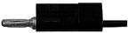 ________________ ________________
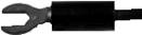 ________________ ________________
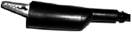 ________________ ________________
|
- Ammeters are always
connected in _______.
The
units of current are _________.
|
- Voltmeters are
always connected in _______.
The
units for voltage are ________.
|
- If the current is
measured as 1 Amp at the power supply, and three identical resistors are
connected in series, what is the current through a single resistor?
- 1 A
- 1/3 A
- 3 A
|
- If the voltage drop
across the power supply is 100 Volts, and three identical resistors are
connected in series, what is the voltage drop
about a single resistor?
- 100 V
- 0 V
- 33 1/3 V
|
- If the current is
measured as 1 Amp at the power supply, and three identical resistors are
connected in parallel, what is the current through a single resistor?
- 1 A
- 1/3 A
- 3 A
|
- If the voltage drop
across the power supply is 100 Volts, and three identical resistors are
connected in parallel, what’s the voltage drop about a single resistor?
- 100 V
- 0 V
- 33 1/3 V
|
- When a multimeter is
switched to ammeter setting, why is one lead always plugged into “A”
(amp) instead of “mA” (milliamp) when you are not sure which you should
choose?
a.
Amps is the generally the correct value
b.
mA is such a small unit the meter may display an error
c.
Each setting has a fuse and the Amp setting is less likely
to exceed the maximum value
d.
this is just the convention
|
|
¼
Problem Bonus
T
/ F Only voltmeters (as opposed to
ammeters) ALWAYS have one of the two plugs (leads) plugged in the “Common”.
|
|
|
|
|
|
|